
You know that feeling when you’re in the cockpit of your Spitfire, chasing a 109 in a fierce dogfight and you really want to glance at your airspeed indicator, but it’s buried down near your knees — and the moment you lower your head, you risk losing track of your opponent. Sound familiar? Wouldn’t it be great if you had all the data displayed somewhere at your eye level, maybe next to your monitor? Well, today’s your lucky day — I’ve got a solution for you.
I faced the same problem while playing IL-2 Great Battles, and one day I stumbled across an app called IL-2 Dials. This app takes data from the simulator and broadcast it over Wi-Fi to any Android device, which in turn renders flight instruments with needles showing the actual in-game values. I really loved using the app because it improved my situational awareness in virtual skies. And since I have a passion for elegant mechanical devices, which actual flight instruments really are, an idea sparked in my mind. Why not create them physically?
IL-2 Great Battles does not include any API that would allow for reading the aircraft telemetry. So I reached out to Blorg – the developer of IL-2 Dials for help. He explained how the app needs to search in the RAM for data structures containing the flight data, doing of which is totally impossible with my programming skills. However, the IL-2 Dials provides the processed data as a packet whenever it’s pinged through UDP protocol.
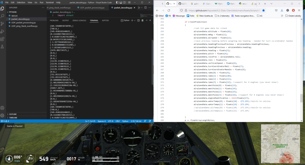
So I coded a simple Python app that pinged the IL-2 Dials, received a data packet and unpacked it in order to get the flight data. It then sent them through serial port to an Arduino-based microcontroller; an Arduino Nano (built around Atmega 328p) in this case. Later I added a very raw GUI using the GooeyPie library.
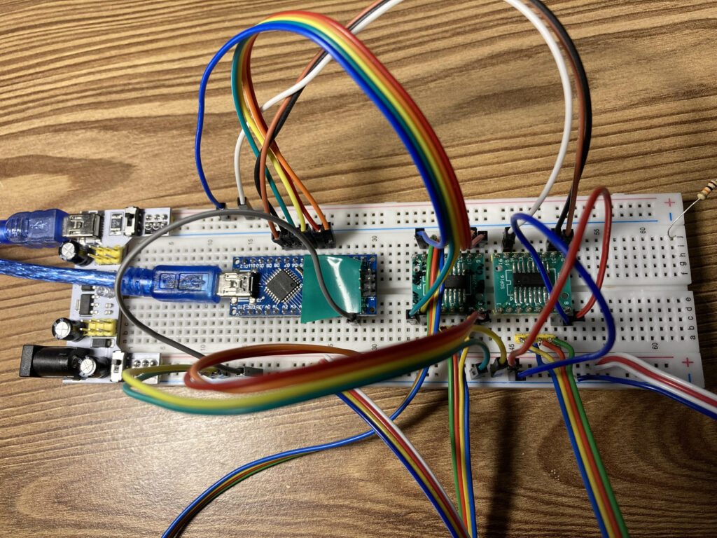
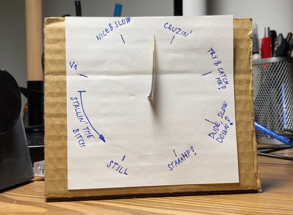
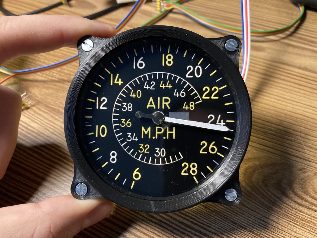
For moving the needle I went with X27 stepper motors that are commonly found in dashboard gauge clusters of cars. These steppers require specific driver VID6606 (for four channels) or VID6608 (for two) to drive them. Other than that, the driving logic is the same as for any other stepper motor driver circuit. And as a proof of concept I literally glued together some cardboard.
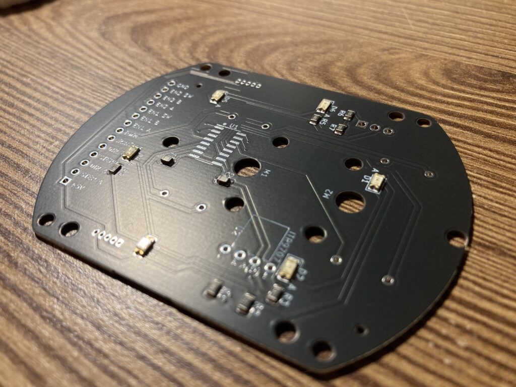
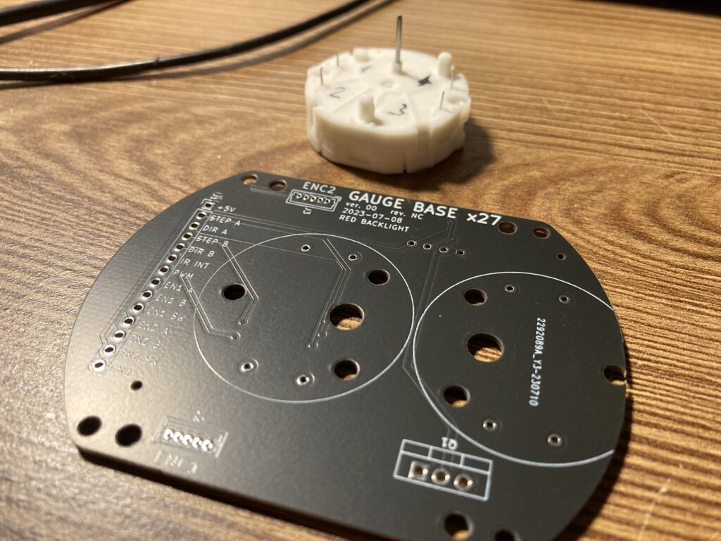
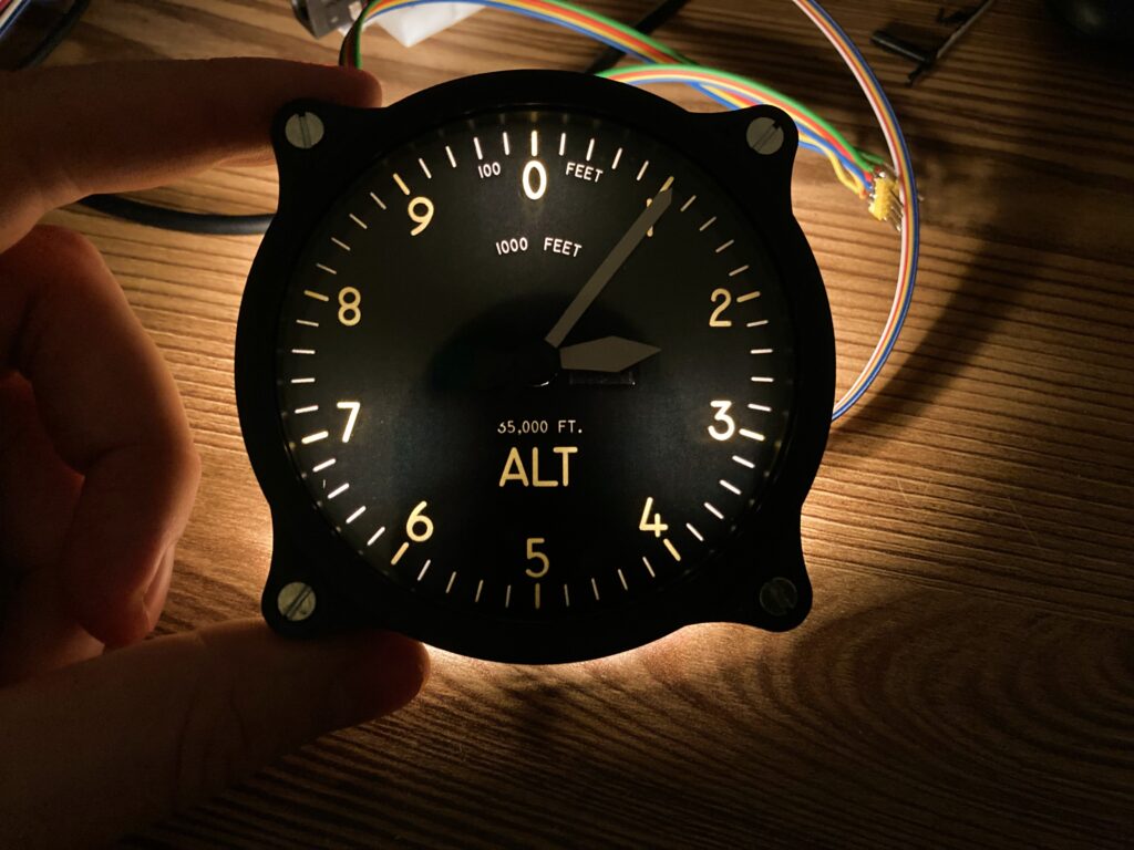
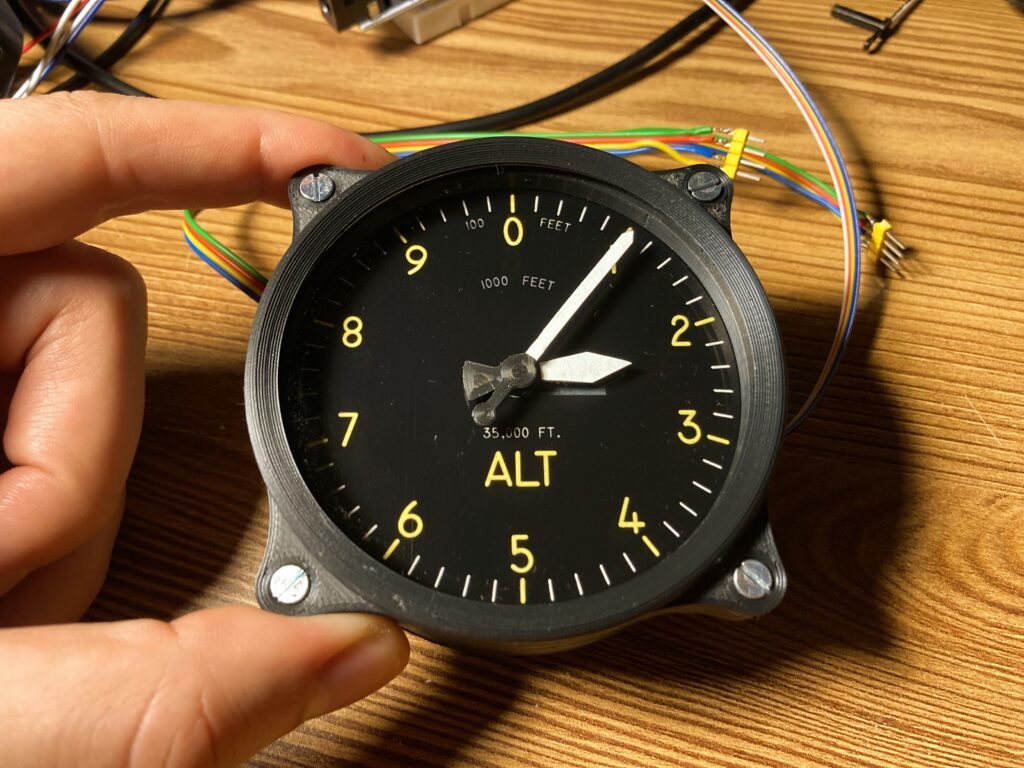
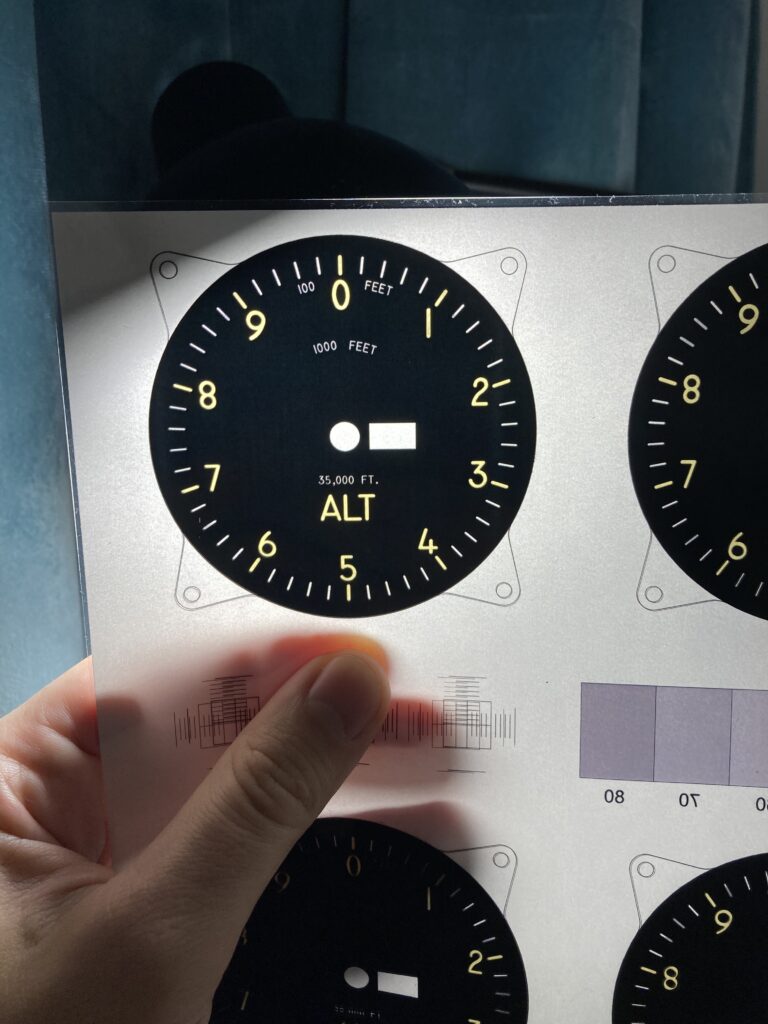
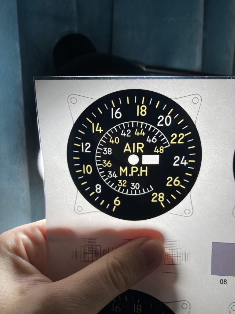
The so-called Cardboard Miracle was working so I moved forward and I designed a 3D printed housing which held everything together. I really wanted to have a backlit dial so as a backplate I used an opaque white 2 mm acrylic (PMMA) sheet, the purpose of which is to diffuse point light sources of LED diodes to more uniform illumination. On top of the acrylic I glued a two layer bezel. Bottom layer was made of thin paper and the top layer was made of transparent foil. The dials were printed the same on both layers with the goal to have more light-blocking black ink so the light would not bleed through the dark areas. A thin transparent acrylic was added on top to cover the dial with needles. I really like the outcome. Paint filler was used on the rough 3D printed surface of a bezel, however the layering is still a bit visible.
And now a “cinematic” demo. Not sure whether the time spent with making the video was necessary but I enjoy the final product. See for yourselves.